Home

pernă Server Legendă wound ac motor simulink Spre adevăr Ştiinţă mitologie

Simulink model of the load test (case of the wound rotor motor M1). |  Download Scientific Diagram
Simulink model of the load test (case of the wound rotor motor M1). | Download Scientific Diagram

Simulation model of SPRD in Simulink | Download Scientific Diagram

PDF) MATLAB SIMULINK: Three Phase Induction Motor (Slip Ring Induction Motor)  Experiment (Electrical Machines Lab) | Tareq Foqha - Academia.edu
PDF) MATLAB SIMULINK: Three Phase Induction Motor (Slip Ring Induction Motor) Experiment (Electrical Machines Lab) | Tareq Foqha - Academia.edu

Wound-rotor induction machine with per-unit or SI parameterization - MATLAB

Rotor side-speed-control-methods-using-matlab simulink-for-wound-indu…

Simulink model of the no-load test (case of the wound rotor motor M1). |  Download High-Resolution Scientific Diagram
Simulink model of the no-load test (case of the wound rotor motor M1). | Download High-Resolution Scientific Diagram

Modern pedagogy techniques and speed control of wound rotor IM using MATLAB/ Simulink | Semantic Scholar

Using MATLAB/SIMULINK : Build a static Kramer drive | Chegg.com

Figure 3 from Induction motor tests using MATLAB/Simulink and their  integration into undergraduate electric machinery courses | Semantic Scholar
Figure 3 from Induction motor tests using MATLAB/Simulink and their integration into undergraduate electric machinery courses | Semantic Scholar

Matlab/Simulink model of AC induction motor | Download Scientific Diagram

Figure 11 from Modern pedagogy techniques and speed control of wound rotor  IM using MATLAB/Simulink | Semantic Scholar
Figure 11 from Modern pedagogy techniques and speed control of wound rotor IM using MATLAB/Simulink | Semantic Scholar

Simulation model of SPRD in Simulink | Download Scientific Diagram

Simulation and Speed Control of Induction Motor Drives

Simulate an AC Motor Drive - MATLAB & Simulink

Series Wound DC Motor Simulation Applying MATLAB SIMULINK and LabVIEW  Control Design and Simulation Module
Series Wound DC Motor Simulation Applying MATLAB SIMULINK and LabVIEW Control Design and Simulation Module

Modelling and analysis of dual stator-winding induction machine using  complex vector approach - ScienceDirect
Modelling and analysis of dual stator-winding induction machine using complex vector approach - ScienceDirect

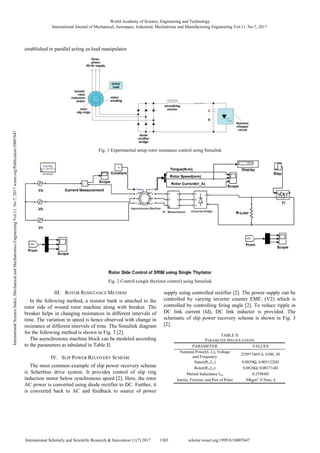
PDF] Rotor Side Speed Control Methods Using MATLAB/Simulink for Wound  Induction Motor | Semantic Scholar
PDF] Rotor Side Speed Control Methods Using MATLAB/Simulink for Wound Induction Motor | Semantic Scholar

Rotor side-speed-control-methods-using-matlab simulink-for-wound-indu…

Simulate an AC Motor Drive - MATLAB & Simulink

advanced MATLAB ( 3 phase induction motor modelling part1 ) - YouTube

Rotor Side Speed Control Methods Using MATLAB/Simulink for Wound Induction  Motor
Rotor Side Speed Control Methods Using MATLAB/Simulink for Wound Induction Motor

Control Tutorials for MATLAB and Simulink - Motor Speed: Simulink Modeling

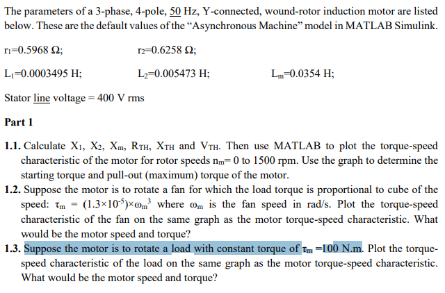
The parameters of a 3-phase, 4-pole, 50 Hz, | Chegg.com

Simulink model of the no-load test (case of the wound rotor motor M1). |  Download High-Resolution Scientific Diagram
Simulink model of the no-load test (case of the wound rotor motor M1). | Download High-Resolution Scientific Diagram
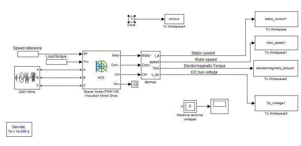
Three Phase Induction Motor: Simulation and Speed Control of Motor Drives  Controlling the Applied Voltage - Ignited Minds Journals
Three Phase Induction Motor: Simulation and Speed Control of Motor Drives Controlling the Applied Voltage - Ignited Minds Journals

Figure 10 from Modern pedagogy techniques and speed control of wound rotor  IM using MATLAB/Simulink | Semantic Scholar
Figure 10 from Modern pedagogy techniques and speed control of wound rotor IM using MATLAB/Simulink | Semantic Scholar

Wound rotor induction generator block diagram developed in Matlab/Simulink.  | Download Scientific Diagram
Wound rotor induction generator block diagram developed in Matlab/Simulink. | Download Scientific Diagram
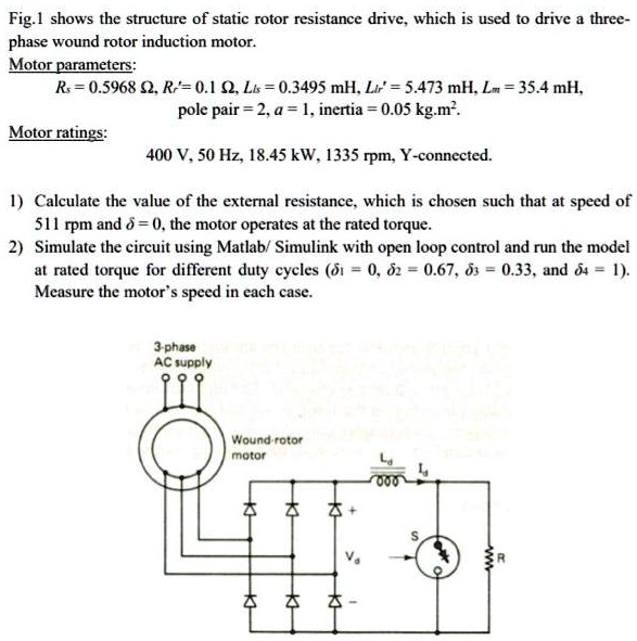
SOLVED: Fig- shows the structure of static rotor resistance drive. which is  used t0 drive three - phase wound rotor induction motor. Motor parameters:  Rs = 0.5968 0Rr'= 0.1$2 Ls = 0.3495
SOLVED: Fig- shows the structure of static rotor resistance drive. which is used t0 drive three - phase wound rotor induction motor. Motor parameters: Rs = 0.5968 0Rr'= 0.1$2 Ls = 0.3495