Home

Tun casă ei 555 timer circuit pcb layout arbitrage Confrunta A se familiariza

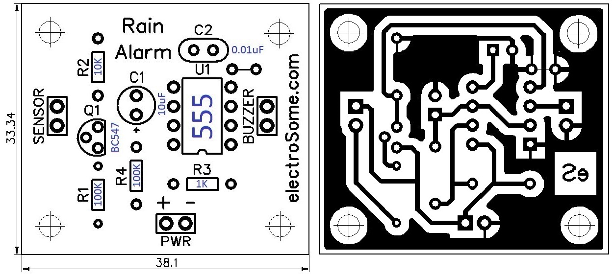
Rain Alarm using 555 Timer - Hobby Circuit

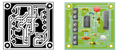
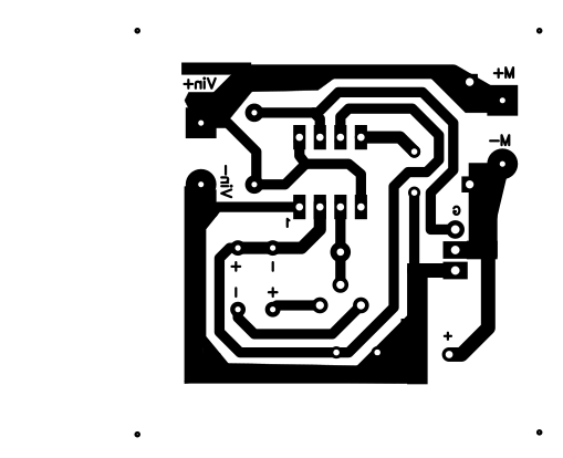
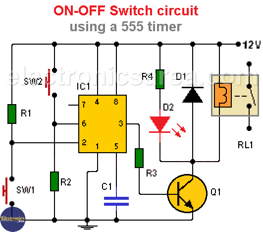
ON-OFF Switch circuit using a 555 timer (PCB) - Electronics Area

555 timer IC Electronic circuit Astable multivibrator Integrated Circuits &  Chips, 555, angle, electronics, text png | PNGWing
555 timer IC Electronic circuit Astable multivibrator Integrated Circuits & Chips, 555, angle, electronics, text png | PNGWing
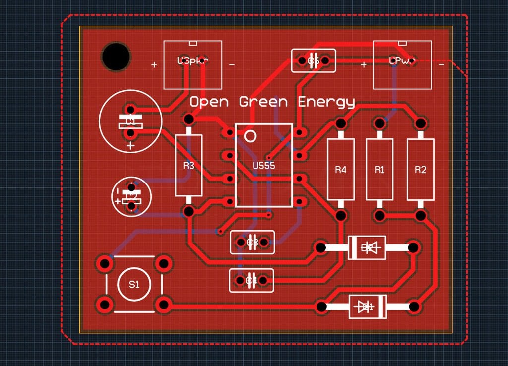
Simple 555 Timer 'Door Bell' is Great for Learning Autodesk Circuits, PCB  Layouts @ADSKCircuits « Adafruit Industries – Makers, hackers, artists,  designers and engineers!
Simple 555 Timer 'Door Bell' is Great for Learning Autodesk Circuits, PCB Layouts @ADSKCircuits « Adafruit Industries – Makers, hackers, artists, designers and engineers!

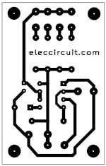
5-20 minuts timer circuit using IC 555 - ElecCircuit.com

Solved: Advice on pcb design and schematic layout of an astable  multivibrator - Autodesk Community - EAGLE
Solved: Advice on pcb design and schematic layout of an astable multivibrator - Autodesk Community - EAGLE

The general 555 timer circuit schematic At the heart of the circuit is... |  Download Scientific Diagram
The general 555 timer circuit schematic At the heart of the circuit is... | Download Scientific Diagram

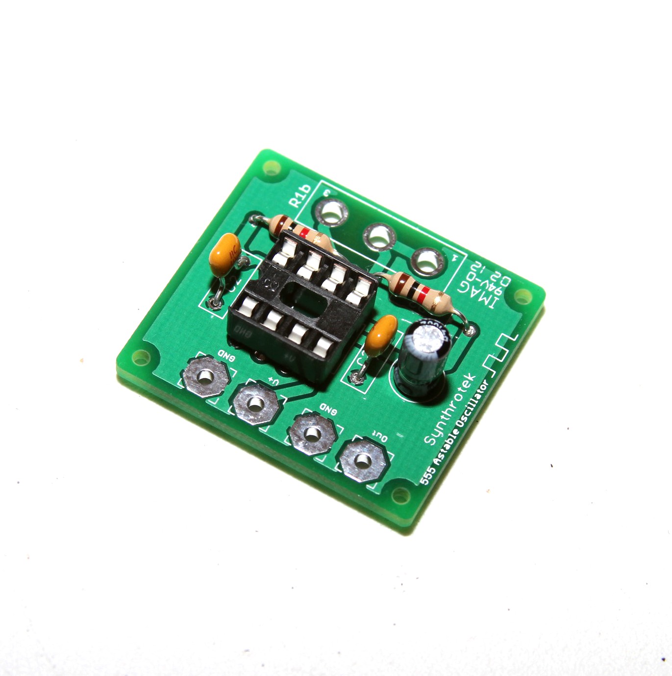
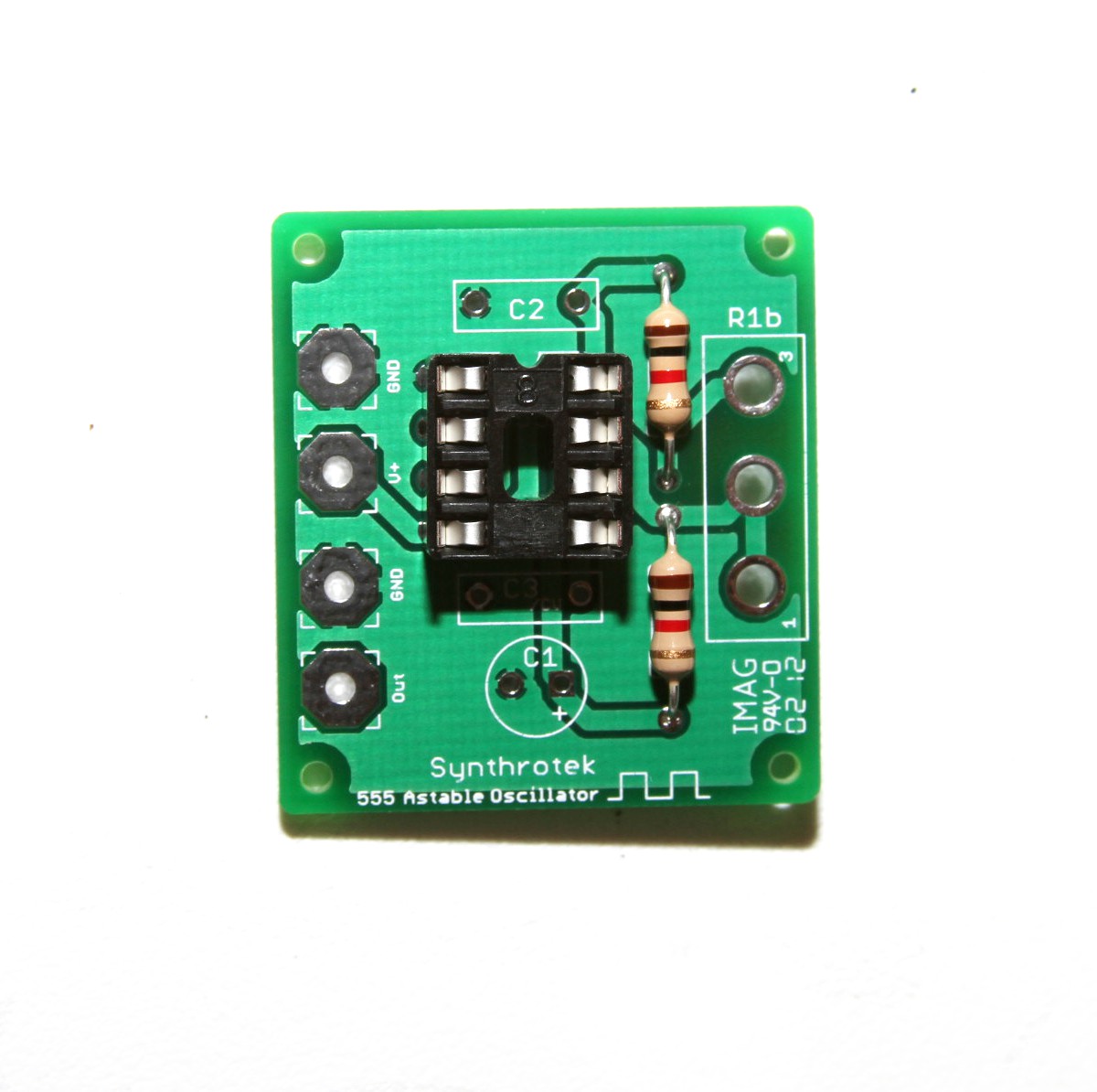
555 Timer Assembly Instructions | Synthrotek

How To Test NE555 | Astable 555 timer circuit + pcb - Share Project - PCBWay

Solved: Advice on pcb design and schematic layout of an astable  multivibrator - Autodesk Community - EAGLE
Solved: Advice on pcb design and schematic layout of an astable multivibrator - Autodesk Community - EAGLE

Simple Electronic Piano using 555 Timer - Toy Organ Circuit

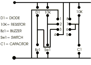
Circuit Diagram to PCB 2

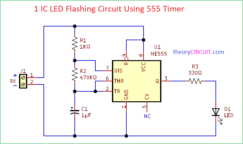
1 IC LED Flashing Circuit Using 555 Timer

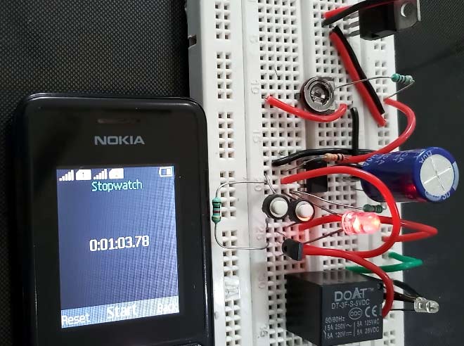
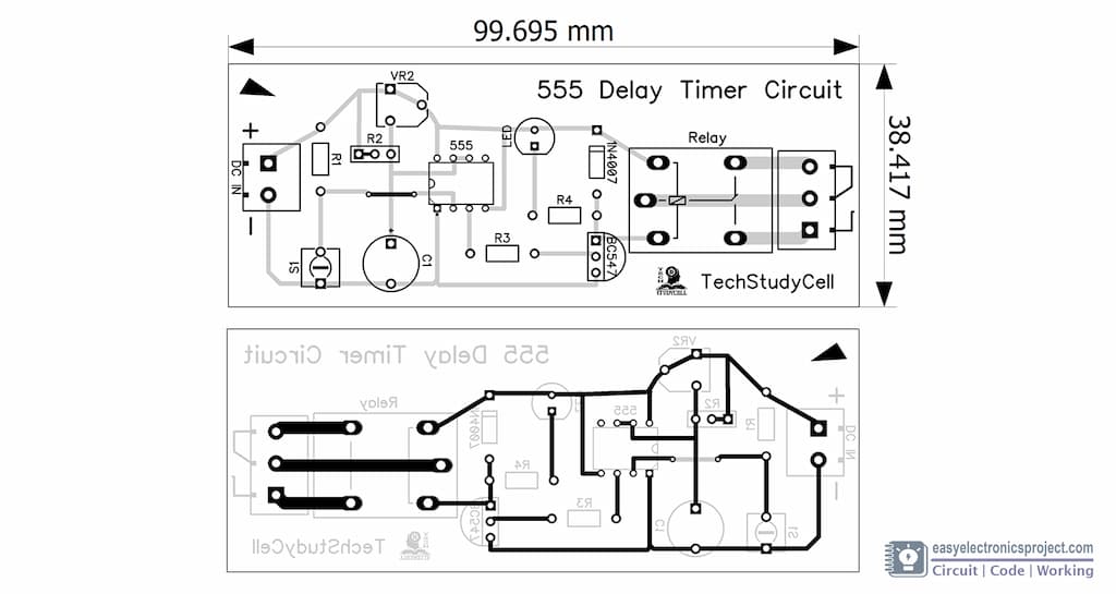
Simple Time Delay Circuit Diagram using 555 Timer IC

555 Timer IC - Types, Construction, Working & Applications

Time Delay Relay circuit using 555 timer IC - Share Project - PCBWay

PCB BOARD DESIGN FOR LED FLASHER USING 555 TIMER IC - DO IT YOURSELF  STUDENT PROJECTS - YouTube
PCB BOARD DESIGN FOR LED FLASHER USING 555 TIMER IC - DO IT YOURSELF STUDENT PROJECTS - YouTube

NE555 based PWM DC Motor Speed Controller Circuit with PCB Layout

Ultrasonic transmitter circuit using IC 555 - Gadgetronicx

How to Make a 555 Timer Blink Circuit on a PCB! : 7 Steps (with Pictures) -  Instructables
How to Make a 555 Timer Blink Circuit on a PCB! : 7 Steps (with Pictures) - Instructables

ON-OFF Switch circuit using a 555 timer (PCB) - Electronics Area

Time Delay Relay circuit using 555 timer IC - Electronics Projects

555 Timer Assembly Instructions | Synthrotek

Time Delay Relay circuit using 555 timer IC - Electronics Projects

Time Delay Relay using 555 Timer, Proteus Simulation and PCB Design